|
Forces Acting on a Gasketed Joint
|
 The
Internal Pressure:
These are the forces continually trying to
unseal a gasketed joint by exerting pressure
against the gasket (blowout pressure) and
against the flanges holding the gasket in
place (hydrostatic end force). See Figure 1 The
Internal Pressure:
These are the forces continually trying to
unseal a gasketed joint by exerting pressure
against the gasket (blowout pressure) and
against the flanges holding the gasket in
place (hydrostatic end force). See Figure 1
 The
Flange Load: The total force
compressing the gasket to create a seal,
i.e., the effective pressure resulting from
the bolt loading. The
Flange Load: The total force
compressing the gasket to create a seal,
i.e., the effective pressure resulting from
the bolt loading. |
 |
 Temperature:
Temperature creates thermo-mechanical
effects, expanding or contracting the metals,
affecting the gasket material by promoting "creep
relaxation" which is a permanent strain or
relaxation quality of many soft materials under
stress.The effect of certain confined fluids may
become increasingly degrading as temperature rises
and attack upon organic gasket materials is
substantially greater than at the ambient
temperatures (about 75°F). As a rule, the higher the
temperature, the more critical becomes the selection
of the proper gasket. Temperature:
Temperature creates thermo-mechanical
effects, expanding or contracting the metals,
affecting the gasket material by promoting "creep
relaxation" which is a permanent strain or
relaxation quality of many soft materials under
stress.The effect of certain confined fluids may
become increasingly degrading as temperature rises
and attack upon organic gasket materials is
substantially greater than at the ambient
temperatures (about 75°F). As a rule, the higher the
temperature, the more critical becomes the selection
of the proper gasket.
 Medium:
The liquid or gas against which the gasket is
to seal. Medium:
The liquid or gas against which the gasket is
to seal.
 General
Conditions:
The type of flange, the flange surfaces, the type of
bolt material, the spacing and tightness of the
bolts, etc. General
Conditions:
The type of flange, the flange surfaces, the type of
bolt material, the spacing and tightness of the
bolts, etc.
Each of
these factors require consideration before an
effective gasket material is finally chosen.
However, the proper gasket may often be rejected
because failure occurred due to a poorly cleaned
flange face, or improper bolting-up practice. These
details require careful attention, but if complied
with will help eliminate gasket blow-out or failure.
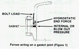
 There
are three principal forces acting on any gasketed
joint. They are: Bolt load and/or other means of
applying the initial compressive load that flows the
gasket material into surface imperfections to form a
seal. The hydrostatic end force, that tends to
separate flanges when the system is pressurized.
Internal pressure acting on the portion of the
gasket exposed to internal pressure, tending to blow
the gasket out of the joint and/or to bypass the
gasket under operating conditions. There are other
shock forces that may be created due to sudden
changes in temperature and pressure. Creep
relaxation is another factor that may come into the
picture. There
are three principal forces acting on any gasketed
joint. They are: Bolt load and/or other means of
applying the initial compressive load that flows the
gasket material into surface imperfections to form a
seal. The hydrostatic end force, that tends to
separate flanges when the system is pressurized.
Internal pressure acting on the portion of the
gasket exposed to internal pressure, tending to blow
the gasket out of the joint and/or to bypass the
gasket under operating conditions. There are other
shock forces that may be created due to sudden
changes in temperature and pressure. Creep
relaxation is another factor that may come into the
picture.
 Figure
1 indicated the three primary forces acting upon a
gasketed joint which we will consider for this
discussion. The initial compression force applied to
a gasket seating surfaces regardless of operating
condition. Initial compression force must be great
enough to compensate for the total hydrostatic end
force that would be present during operating
conditions. It must be sufficient to maintain a
residual load on the gasket/flange interface. From a
practical standpoint, residual gasket load must be
"X" time internal pressure if a tight joint is to be
maintained. This unknown quantity "X" is what is
known as the "," factor in the ASME unfired pressure
vessel code and will vary depending upon the type of
gasket being used. Actually the "m" value is the
ratio of residual unit stress (bolt load minus
hydrostatic end force) on gasket (psi) to internal
pressure of the system. The larger the number used
for "m," the more conservative the flange design
would be, and the more assurance the designer has of
obtaining a tight joint.
>>The End Figure
1 indicated the three primary forces acting upon a
gasketed joint which we will consider for this
discussion. The initial compression force applied to
a gasket seating surfaces regardless of operating
condition. Initial compression force must be great
enough to compensate for the total hydrostatic end
force that would be present during operating
conditions. It must be sufficient to maintain a
residual load on the gasket/flange interface. From a
practical standpoint, residual gasket load must be
"X" time internal pressure if a tight joint is to be
maintained. This unknown quantity "X" is what is
known as the "," factor in the ASME unfired pressure
vessel code and will vary depending upon the type of
gasket being used. Actually the "m" value is the
ratio of residual unit stress (bolt load minus
hydrostatic end force) on gasket (psi) to internal
pressure of the system. The larger the number used
for "m," the more conservative the flange design
would be, and the more assurance the designer has of
obtaining a tight joint.
>>The End
|